|
LOCK
FORMER
|
|||||
 |
|||||
How to use a Pittsburgh Lockformer Machine:
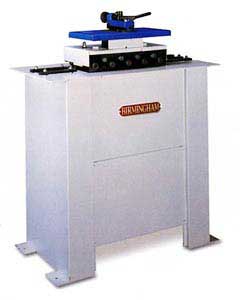
These instructions are written for a Birmingham PITTSBURGH LOCKFORMER MACHINE designed for HVAC duct making fabricators but may also be useful for understanding how to use many other brands of Pittsburgh type rollforming Machines.

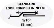
Pittsburgh
Lock formed in sheet metal

The machine has 2 sides to it. One side has the Pittsburgh rolls already installed and the other side is available for installing one of the optional roll sets (such as right angle flanging, drive cleat or ACME double seam). Installing a set of optional rolls is the customer's responsibility. Please note; the optional rolls must be installed in their correct order, otherwise they will not function and could have a dangerous reactionwhen sheet metal is fed into them.
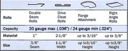
Each machine has a capacity range that is very important to be aware of. Most HVAC Pittsburgh lockforming machines do a decent job or forming over a 4 gauge range of sheet metal thicknesses, such as 20 to 24 gauge, or 24 to 28 gauge. But some American made machines can form 6 gauges of metal, such as 20 to 26 gauge. There are also some that can roll a Pittsburgh lock on 18 gauge or 16 gauge. So carefully consider the range you will work with when buying one.
WARNING: ALWAYS KEEP HAIR, CLOTHING, HANDS AND FINGERS AWAY FROM THE MOVING ROLLS THAT ARE INSIDE THE FORMING HEAD !
Operating Instructions:
To
Use the machine:
Turn the machine on. Holding the material you want to form against
the angle gauge bar, slide it into the forming head. Be sure keep
the material against the gauge bar until the forming work is finished.
The machine will form a Pittsburgh type shape into the edge of sheet
metal that is 24gauge(.024")[.64mm], 22gauge(.030")[.76mm],
or 20gauge(.036")[.91mm] thick. The optional rolls have the same
capacities. Though the machine was originally designed for 26 gauge
metal also, the machine is bad for 26 gauge sheet metal.
Note:
This machine will handle sheets 7" and longer. If you need shorter,
leave sheet metal as a longer piece, run it through the machine, and
then notch and cut after forming.
Make "Hold-Down Adjustment" to compensate for any variation in the
material. But do not adjust unless the material slips, or tends to
move away from the gauge, or curls up at the end.
TO
ADJUST:
1. Remove top cover.
2. Tighten hold-down studs until snug and then loosen them a quarter
turn. (This setting will usually give proper adjustment for all thicknesses
of material.)
3. If the material slips, tighten the studs equally until the condition
is overcome. If the material curls up after leaving the forming head,
or shows extremely heavy pressure marks, loosen studs slightly. If
a wider or narrower hammer-over edge is desired, the angle gauge on
the right hand side can be moved to give the desired width. When moving
this gauge, be sure to move both ends the same distance, keeping it
parallel to the front edge of the top plate of the machine.
DO NOT MOVE ANGLE GAUGES ON THE LEFT OR FINISHING END OF THE MACHINE.
THESE GAUGES ARE NOT INTENDED TO TOUCH THE MATERIAL AS IT COMES THROUGH.
It is very important that long sheets be fed into the machine flat
and against the angle gauge for the start.
IMPORTANT: If proper care is taken, the small knife edge roll that
holds the pocket of the Pittsburgh Lock open will not break. If burrs
and twists from snip cuts are not flattened out, it will sometimes
strike against the opening roll causing it to break.
Lubrication: There are six alemite fittings located on the underside of the stand roller case on the auxiliary side of the machine. These fittings lubricate the main reduction bearings and should be lubricated after every four hours of operation.
Recommended lubricant: Standard Viscous #3 (Product of the Standard Oil Company) or equivalent. The slow speed shafts do not require additional lubrication. Grease gears periodically or as needed. If you need to be use the machine outside, an oil or grease film may prevent rusting of surfaces. Better to use inside.
TO
OPERATE AUTO-GUIDE POWER FLANGING ATTACHMENT AND ADJUST UNIT FOR GAUGE
MATERIAL THICKNESS TO BE USED
To adjust clearance between flanging rolls, tighten the adjusting
screw on the front of the block of the machine all the way, then loosen
the screw approximately one eighth of a turn. (This setting is usually
correct for 24 gauge material.) Do not set front gauge adjusting screw
too tight. It should be set just tight enough to draw the metal through
the rolls. Too tight a setting will stretch and wrinkle the material.
To adjust the spring tension on the compensator arm, tighten the adjusting
dial on the back side of the flanger to the stop and then turn back
to the proper gauge setting shown on the adjusting dial.
TURN UP A "STARTING FLANGE" On the material before inserting it into the rolls. This is done by inserting the leading edge of the work to be flanged in the slot cut into the table and bending the piece away from the operator approximately 45°. Start the leading edge of the material into the rolls. As the material passes through the rolls, the compensator arm will make contact with the material and guide it through the rolls. If the material pulls out of the rolls, it is an indication that either the front adjusting screw is too loose or the back adjusting dial is not tight enough.
IMPORTANT: When starting a partially formed section that contains an inside curve, push the compensator arm back until it locks out of position. Feed partially formed section into the rolls and the machine will pull the material through. As the rolls approach the section that is not formed, bring the compensator arm to material holding the spring tension off the piece until the unformed section comes to the rolls,; then apply pressure to the piece until the flange picks up, then release compensator arm so that "automatic" guiding is resumed.
DOUBLE
SEAM or STRAIGHT RIGHT ANGLE FLANGE ROLLS
1. Remove top cover.
2. Remove rear section of top plate. This will expose the extended
shafts on which the rolls are to be mounted.
3. Select the first pair of rolls, which are marked "T1" and "B1",
and slip them on the shafts at the left, or feed side of the machine,
placing "T1" on the upper shaft and "B1" on the lower. Repeat this
procedure with rolls "T2" and "B2"' "T3" and "B3"; "T4" and "B4";
"T5" and "B5" until all rolls have been mounted. All rolls marked
"T" should be on the top shafts and "B" rolls on the bottoms shafts,
in numerical order, reading from left to right, facing outward.
THE NUMBERED SIDES MUST FACE OUTWARD, OR TOWARD THE OPERATOR.
4. Fasten rolls to shafts with capscrews and special washers which
are provided.
5. Mount gauge on starting side of machine, using slotted holes provided
in top plate. The position of this gauge is shown below (Gauge Dimensions).
The angle gauge on the finishing side should be flush against the
metal as it emerges from the rolls.
6. Replace back plate and top cover.
7. Hold material against gauge and feed into machine.
DRIVE
CLEAT ROLLS:
1. Proceed as instructed for Double Seam Rolls, but leave roll "T-2"
loose. This roll centers itself and should not be held in place with
cap screw. Woodruff keys are used to hold the rolls to the shafts
in all cases, however.
2. Remove stud indicated by arrow below (this is located between "B4"
and "B5") and place the slide block in position, securing it with
the 3" stud furnished.
CAUTION: ALWAYS REMOVE THE SLIDE BLOCK AND REPLACE THE SHORT STUD
WHEN TAKING THE DRIVE CLEAT ROLLS OFF THE MACHINE.
3. Mount the feed gauge on left hand side so that it is exactly centered
with the rolls. THIS IS VERY IMPORTANT! If it is not centered,
the cleat will not be perfect.
4. Tighten small hold-down studs so that "T5" and "B5" do not separate
when drive cleats are passing through. IMPORTANT: Be sure to cut your
material a full 2 1/8" wide to insure that it forms correctly.
|
Birmingham
Pittsburg Type Lockformer Machines
Click to request a formal quote Call 773-334-5000 to order this machine. Model L-20 Features:
OPTIONS: |
|

Click to go to our HVAC Tools webpage
Click for American Machine Tools Company Homepage
5862 Northwest Hwy
Chicago IL 60631 USA
Phone: 773-334-5000
Fax: 773-442-0314
Click to email us
American Machine Tools Co.
All rights reserved
Offers from American Machine Tools Corporation include include Terms and Conditions shown on our website.
Liability is strictly limited to those warranties of fitness for purpose and safety as provided by the manufacturer.
Products and Logos in this website are trademarks or registered trademarks of their respective companies or mark holders.