|
Sheet
Metal Brake
|
|||||
 |
|||||
Instructions How to use a Sheet Metal Brake Machine
Click for Chicago Sheet Metal Hand Brake Machines
Here we explain
how to use and adjust a sheet metal brake. We also explain how to make
a sheet metal box or pan. It is also possible to bend and flatten a hem,
to form a radius, and to bend a zig-zag. The standard procedure for making
a simple bend in sheet metal using a hand brake machine is as follows:
1. Insert sheet metal under clamping bar.
2. Adjust clamping handle cam for metal thickness.
3. Measure and position the sheet metal edge the correct distance parrallel
to the clamping bar.
4. Pull down the clamping handles at each end to clamp the metal in place.
5. Set the stop rod to stop the bend apron at the angle you want (usually
90 degrees).
5. Bend at your knees and lift the 2 handles under the apron until the
stop rod stops the apron.
6. Slowly bring the apron back down. Release the clamping handles.
See below for more information about how to bend a box or pan shape. Another common use for the machine is hemming. Start by bending your metal to 135 degrees and then flatten a hem against the top of the clamping bar using the apron all the way against it. If the sheet metal is very thin you can instead flatten the hem under the clamping bar.
Though the original manufacturer probably took precautions to have adjustments on the hand brake set properly to most metal work, sometimes after handling and transportation, or years of use, they may occassionally require some adjustment. The instructions shown here were originally written for a Chicago Hand Brake Machine, but most other hand brakes are a copy of their famous design, and therefore are similar. But please be aware that the copies are usually missing certain small features and geometry that have made the Chicago design superior since 1899. Please note: The capacity of Hand Brake machines to bend sheet metal is normally limited to 12 gauge (.105" = 2.7mm) metal thickness on heavy duty models and 16 gauge (.06" = 1.5mm) on light duty models. 10 foot are limited to 14 gauge and 12 foot capacity machines are limited to 18 gauge. Some Chinese made copies may have lower capacity due to cheaper construction.
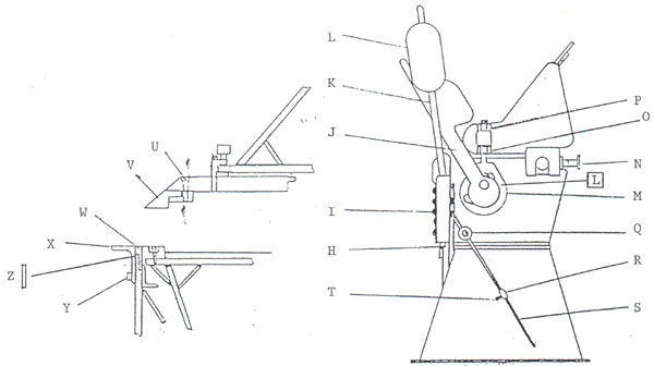
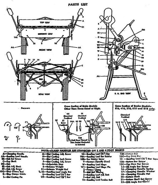
| A.
Machine Leg B. Bend Handle C. Nut D. Nut E. Nut F. Nut G. Nut H. Hinge Adjustment Screw Q. Guide Ring |
I.
Hinge Bolt J. Clamp Handle K. Rod L. Counterweight M. Link N. Top Adjustment Handle O. Nut P. Nut R. Gauge Stop |
S. Gauge Rod T. Gauge Screw U. Finger Screw V. Nose Bars W. Insert Bar X. Angle Bar Y. Hex. Socket Screw Z. 1/4" Insert Bar |
To check your machine, see that the Brake sets level on the floor, so that top leaf does not creep forward when clamping. If the top leaf does creep forward when clamping first, check the tightness of set screw (P) and cap screw (O). If this does not remedy the creeping, place a wedge under the rear of the leg, on side that creeps. Bring the wedge in until this creeping is eliminated, then replace the wedge with a permanent block of the correct height.
Check the bending leaf and see that the edge is (1/64") below the bed edge when the bending leaf is in the down position. This edge should be (1/64") below the bed edge on the ends and (1/32") lower in the center. The bending leaf ends can be lowered by tightening set screw (J). To raise ends of bending leaf, tighten set screw (H). To lower the bending leaf in center, tighten truss rod bolt (7). To raise bending leaf in center, tighten truss rod bolt (2).
If sheet bends over further on one end than the other, set the top leaf back on end where sheet is bent over too far. This is done by loosening cap screw (O), and setting adjustment with set screws (P) and (M).
Bending leaf may become bowed in center after use. This can be straightened out quickly by tightening both bolts (10) until center is brought into a straight line.
Adjustment for clamping different thickness of metal is made by loosening set screw (BB) which holds link block (EE), and adjusting set screw (FF) until the desired pressure is obtained, when clamping on the thickness of metal to be bent. When this adjustment is made, tighten set screw (BB).
Set the top leaf back at bending edge twice the thickness of the metal for bending within four gauges of capacity. Move forward proportionately on lighter material if sharper bends are desired. This adjustment is made by loosening cap screw (O) an adjusting set screws (M) and (P), as required. It is important that cap screw (O) be tightened after the upper jaw is set to its correct point.
MOST HAND BRAKE MACHINES ARE RATED FOR 1" (25mm) wide MINIMUM FLANGE ON CAPACITY MATERIAL. MACHINE CAN BE USED FOR CAPACITY BENDING ONLY WHEN ANGLE BAR (S-SS) IS IN PLACE IN THE STANDARD POSITION.
When Bar (U-6) 1/2" bending edge is in place, the capacity of the machine is reduced by four gauges. This means a 12 gauge capacity machine becomes a 16 gauge machine and a 14 gauge machine becomes a 18 gauge machine. When this (U-6) bar is used, the angle bar (SS) must be set in the low position. When Bar (U-5) 1/4" bending edge is in use, the capacity of the Brake is reduced seven gauges and the angle bar ( SS) should be in the low position. Holes are provided in bending leaf and in angle bar for attaching this angle bar in the low position for making narrow offset bends. (U-5) 1/4" bar should not be used for anything other than to bend narrow reverse flanges on material not heavier than seven gauges less than the capacity of the machine. Capacity ratings according to the thickness of bending leaf edges apply to all sizes.
SHORT PIECES OF MATERIAL SHOULD BE BENT IN THE CENTER OF THE BRAKE. THIS EQUALIZES THIS STRAIN. But these machines do not act like a brake press and therefore are not designed for bending narrow pieces of extra thick metal because this would cause a concentrated load on the clamping bar and machine bed which could damage your machine.
NEVER BEND AGAINST SEAMS UNLESS MACHINE IS SET TO CLAMP THE FULL MULTIPLE THICKNESS OF THE SEAM AND THE TOP LEAF IS SET BACK FOR CLEARANCE OF THE FULL MULTIPLE THICKNESS.
Balance weights (R) can be raised or lowered to properly counterbalance the bending leaf.
This adjustable stop gauge (GG) can be used to regulate the angle of the bend when duplicate work is made. This adjustment is made with the stop marked (Q).
*Formers (V) shown below, are attached to the machine as shown on the sketch with the 1/2" clearance side against the bending leaf. This friction clamps (Y) are placed in position and tapped lightly with a mallet. This creates enough friction to hold the formers. To remove clamp, tap upward or turn. Formers can be obtained in half-round sizes: 3", 2 1/4", 1 6/8", 1" and 5/8". Square bends can be made on a number of sheets and the curves bent afterwards on the formers. The wide opening of the jaw permits the sheets passing over the formers.
*Note: Formers are not standard equipment.
When forming cornices or other sections of wide girth, it is advisable to start a bend neat the center or make a kink on the opposite edge from the bend made first to equalizer the buckles in the sheet. The reason for this is that sheets are not perfectly flat and if one edge is left buckled while the other edge is straightened by clamping in the Brake, the bends made later in the buckled part will straighten out this buckle and consequently, throw the first bend out of line.
Bending left handle can be used in two positions. Standard position is shown on front view. By removing bolt (15), handle can be moved over to an outside position that when forming wide sheets the sheet is not in the operator's way.
OIL WORKING PARTS OCCASIONALLY.
OPERATING ADJUSTMENTS
Adjusting for Metal Thickness:
Clearance for bends is obtained by moving Top Leaf back at bending edge. If material to be bent is within four gauges of capacity, move Top Leaf back twice the thickness of the material. With lighter material, move Top Leaf proportionately forward if sharper bends are desired.
1.Unclamp Handles (J) slightly.
2. Adjust Top Leaf with Top Adjustment Handles (N). Clamping pressure of the Links (M) is changes by adjusting the Nuts (O/P).
Duplicate Bends:
Adjustable Stop Gauge (R) may be positioned at any point on Rod (S) by means of Lock Bolt (T) to limit the degree of bend to repeat the desired bend angle.
Counterbalance:
Counterweight (L) can be raised or lowered on Rod (K) to properly counterbalance the Bending Leaf.
Overbending Adjustment:
If sheet bend over further on one side than on the other, set the Top Leaf back on the end where sheet is overbending.
1.Unclamp Handles (J) slightly on side that is overbending.
2. Adjust Top Leaf with Top Adjustment on side that is overbending.
3. Reclamp Handle (J).
Creeping Top Leaf Adjustments:
Should Top Leaf Forward when clamping material:
1. Check that brake sets level on floor.
2. Check Adjustment Bolt Assembly (25) to ensure that Top Adjustment Screw Collars are locked into position so that the Screws cannot move back and fourth in Saddles - front shoulder of Screws and face of Collars must be snug against Saddles with minimum clearance.
3. If still creeping, wedge under rear of Leg (A) at end that creeps until stopped. Replace wedge with permanent block of correct height.
Capacity:
The bending capacity of the brake is determined by the bending edge thickness provided by the Bending Leaf Bars (W/X/Z) when mounted on leaf.
1. Angle Bar (X) allows the full rated 1" minimum flange on capacity material.
2. 1/2" Insert Bat with Angle Bar in LOW position reduces capacity of brake four gauges.
3. 1/4" Insert Bar and Angle Bar in LOW position reduces capacity of brake seven gauges.
Narrow Offset Bends:
Remove Angle Bar (X) and Insert Bar (W)- use 1/4" Insert Bar (Z).
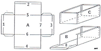
How to Make a Box or Pan Shape:
See diagrams above and below. Make sure that Jaws form a straight bending edge at the Nose Bars (V)
- First layout the shape of your box on a piece of sheet metal. Maybe try it on cardboard first.
- Cut away or notch out the 4 corners of the sheet metal that you will not use.
- Bend the first 2 opposite sides of your box to 90 degrees.
- Remove the 2 fingers that are in the way of bending your 3rd and 4th box sides.
- Set Fingers (39) in partially opened Top Leaf with Screws (36) and Nose Clamp Bar Bolts (U) loose.
- With Angle Bar (X) mounted to Leaf bring up Bending Leaf (1) using it's pressure to straight-line of Nose Bars (see dotted lines in sketch opposite).
- If using our optional Extension Fingers, you can make a reinforced box which is extra rigid.
- Tighten Screws and Clamp Bar Bolts after making sure the gaps between fingers are even.
- Bend up one side at a time using the stop rod set for a 90 degree bend.
- Weld up
the 4 corners of your box.
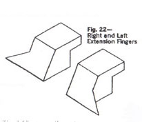 |
Extension Fingers - optional equipment (see Fig. 22) Some Box and Pan capable Hand Brake machines such as Chicago Dreis & Krump have the option of using Extension Fingers in place of the regular box fingers for forming inside corners to make a box shape with a return flange. This is to create a reinforced corner as in picture of the flat blank shown above. One or both Extension Fingers can be used with the other standard fingers in position. |
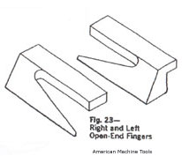 |
Open End Fingers - optional equipment (see Fig. 23) Some Box and Pan capable Hand Brake machines such as Chicago Dreis & Krump have the option of using Open End Fingers in place of the standard fingers. These fingers allow you to make a tube shape on your machine out of thin metal. Tube shapes such as square, rectangular, triangular and tapered can be bent. The formed part can be slipped off the open end of the finger. |
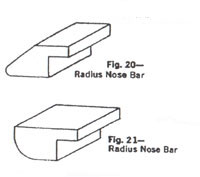 |
Radius Nose Bars for radius bends - optional equipment (see Fig. 20 and Fig. 21) Some Box and Pan capable Hand Brake machines such as Chicago Dreis & Krump have the option of using Radius Nose Bars that mount in place of the standard wedge shape nose bars. Radius nose bars up to 1/2 inch radius are useful when bending high tensile strength aircraft aluminum to prevent the metal from cracking at the bend line. Different sizess are available to create overlapping radius work. Angle Bar (X) and Insert Bar (W) must both be mounted to Leaf to wipe material around Radius Nose Bar. |
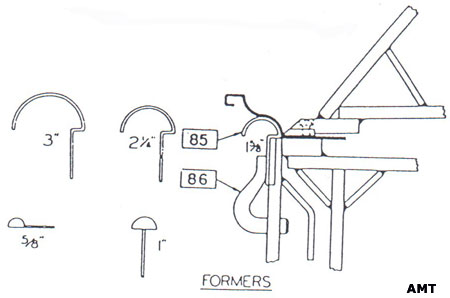
Radius Formers (see picture above) - optional equipment
Some Box and Pan capable Hand Brake machines such as Chicago Dreis & Krump have the option of using Moulds or Formers (85) that can be purchased in half round sizes of 5/8", 1", 1 5/8", and 3 inch radius. These are designed for putting a radius on copper or very thin sheet metal such as 26 gauge (.018"=.5mm). Good for forming architectural mouldings and antique style gutters. Most Hand Brake machines do not have this option. This is an option when you buy a Chicago Dries & Krump Hand Brake.
Attach to the brake machine by means of Formers Clamps (86):
- Place 1/2" clearance side of Former against Bending Leaf as shown in sketch.
- Position Former Clamps and tap lightly with mallet. This creates enough friction to hold Formers.
- To remove Former Clamps tap upward or turn.
Square bends can be made on a number of sheets and curves bent afterwards on Formers. The wide opening of the Top permits these semi-formed sheets to pass over the Formers.
Cautions:
Bend short pieces of material in center of brake to equalize the strain.
Never bend against seams unless Links (M) are adjusted to clamp the full multiple thickness of seam; and Top Leaf is set back for clearance of the same full multiple thickness.
Always have both Angle Bar (X) and Insert Bar (W) mounted to Leaf when making capacity bends.
When forming sections of wide girth such as cornices to equalize the buckles in the sheet:
1. Start bend near the center of sheet, or,
2. Make a kink in the opposite end of sheet from the bend first time.
Sheets are not always perfectly flat and a buckle left in one end while the other is straightened by clamping in the brake, will throw the first bend out of line when it, in turn, is straightened.
Always use material with sqaure-sheared edges- rolled-edges will cause material to bow.
Never use brake to bend rods- these will make a dent in the Nose Bar. The dent will show up as a mark when you bend thin metal or soft metals.
Always adjust for differences in gauges- especially never force-clamp the Top on material heavier than that for which the Links and Top are set by using pipe extensions clamp Handles for Leverage. If you force the Clamping Handle it may eventually break and they are expensive to replace.
Lubrication:
Lubricate occasionally with SAE-30 oil ( Government Specification MIL-O-6081B) where indicated by symbol [L] except for Top Saddle (26), cavities with grease (MIL-L-7870).
Click for How to use a Lathe Machine
Click for How to use a Milling Machine
Click for How to use a Band Saw Machine
Click for the American Machine Tool Homepage
5862 Northwest Hwy
Chicago IL 60631 USA
Phone: 773-334-5000
Fax: 773-442-0314
Click to email us
American Machine Tools Corp.
All rights reserved
Offers from American Machine Tools Corporation include include Terms and Conditions shown on our website.
Liability is strictly limited to those warranties of fitness for purpose and safety as provided by the manufacturer.
Products and Logos in this website are trademarks or registered trademarks of their respective companies or mark holders.