|
Ironworker
- How to
|
|||||
 |
|||||
How To Use a Hydraulic Ironworker Machine:
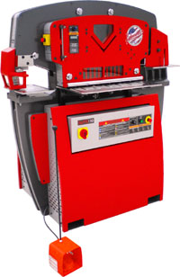
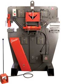
These instructions are written for an Edwards HYDRAULIC IRONWORKER MACHINE but may also be useful for understanding how to use many other brands of Ironworkers. These instructions are written for Hydaulically operated not Mechanical operated machines, though many procedures will be the same.
Often called the swiss-army-knife of machine tools; Ironworker machines are designed to punch, shear, bend and notch mild steel plate, barstock, angle iron and pipe. A wide range of accessories are available to fabricate rod and square stock, sheet metal and pipe. While many of these machines have a pivot arm system that is pulled down by a hydraulic cylinder, the American made Edwards Ironworkers operate by applying hydraulic force to a moving center plate. The center moves within the machine frame in a simple, vertical path and exerts downward force through shear blades, punch and dies, notchers, press brake dies or bump-die tooling to work with steel. Vertical travel of the moving center allows the operator to perform multiple operations on an Edwards Ironworker without always needing to remove adjacent tooling. Though there are some dual operator machines, due to their high cost most Ironworker machines are designed for single operator use only.
|
|
 |
IMPORTANT COMMON SENSE SAFETY PRECAUTIONS
Your Ironworker uses hydraulic pressure and moving shear blades to cut steel products. To operate this tool safely, please review the following safety precautions.
· Read and
understand your Ironworker Operator Manual, Installation Manual, Machine
Safety Manual and Maintenance Manual.
· Use the tool ONLY for its intended operation.
· Wear approved eye protection.
· Wear protective gloves and clothing.
· Use safety guards, material hold-downs and punch stripper supplied with
your Ironworker. Removal, modification or improper use of these safety
devices may result in serious injury and will void your machine warranty.
· Keep away from moving parts during operation.
· Always be ready to lift your foot off the foot pedal to stop a mistake
from seriously injuring you.
· Unplug or lock-out/tag-out your Ironworker before performing and maintenance
or adjustment activities.
· Any maintenance, adjustment or changes in tooling for your Ironworker
must be performed by a qualified individual with the processes and procedures
describes in the Operator Manual.
· Maintain a clean machine. Remove any obstructions, slugs, cut-offs and
fillings from the work area.
· Adequately support the steel material being worked.
· Turn your Ironworker off when not in use-never leave a powered Ironworker
unattended.
MACHINE SETUP
Your Ironworker was bagged, palletized, and shipped from the factory to your dock. Remove the protective packaging and bolts from the tubular legs that secure the machine to its pallet. Move your Ironworker to its fabrication location by inserting your forklift forks within the tubular Ironworker legs. Do not move the machine by any other means! Locate your Ironworker directly adjacent to your power supply. See instructions for elctrical hookup written down below.
CARE AND
PERIODIC MAINTENANCE
Your Edwards Ironworker will benefit from reasonable care and periodic
maintenance.
· Provide
clean ISO Viscosity 46 hydraulic fluid (or equal) to the cylinder in the
Ironworker. Contaminated fluid will compromise your cutting operation.
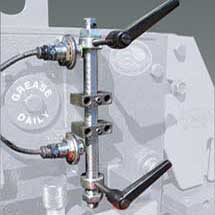
· Grease all machine guides and pins daily. Your Ironworker is labeled
with all grease locations that require maintenance.
· Maintain .010 clearance between fixed and movable shear blades on 40,
50, 55, 60 and 65 Ton models at all times. Maintain .015 clearance between
fixed and movable shear blades on 75, 100, 100D and 120 Ton models at
all times. Insert a feeler gauge between fixed and movable blades to verify
proper blade clearance and shear tolerance. Adjust tolerance of shear
blades by relieving the locking nuts that secure the gib-pins to the Ironworker
frame. Once loose, rotate gib-pins to push the operating center against
the frame. Gap the angle and bar shear blades with the specified clearance
and tighten the gib-pin lock nuts. Failure to maintain proper clearance
will result in lower quality cuts, damage to blade, blade pockets and
potential to damage the Ironworker frame.
· Periodically check gib-pins for lubrication and snugness to operating
center. Tighten gib-pins and locking nuts to maintain blade clearance
as indicated above. Gib-pins are wearing parts. Order replacement gib-pins
through your Edwards Distributor or through Edwards Mfg.Co.
· The blade set for your Ironworker is crafted from S7, heat treated steel.
These are wearing parts that will fail over time. Order additional blade
sets through your Edwards Distributor or through Edwards Mfg. Co.
· Check the hydraulic fluid level regularly. Replace the external oil
filter on your Ironworker after your first 30 hours of use and every 1000
hours thereafter. Change your hydraulic oil every 5000 hours.
· Periodically clean your Ironworker with a compressed air nozzle and
soft cloth. Remove filings, dirt, dust and grime from working surfaces.
· Periodically check tooling for wear. Replace worn tooling* according
to manufacturers literature. If in doubt, call Edwards for advice.
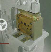
PUNCHING
Your Ironworker is capable of punching materials as listed in the Ironworker Specifications section of this Manual as well as described on the capacity labels positioned at the Punch Station. The punch station on the Edwards Ironworker allows for a wide variety of punching, stamping or embossing applications. The removable table allows for flange or leg down punching of standard channel and angle sections.
Setup
Your Edwards Ironworker has been shipped with a punch and die installed
within the punch station. When changing the punch and dies its important
to make sure the machine is turned off. Failure to power down your machine
could result in injury to the operator performing the work. To setup your
punch station, please observe the following steps.
1. Swing the Punch Stripper up from the punch by loosening the stripper
assembly bolts.
2. Remove punch by loosening the punch nut assembly with factory supplied
wrench.
3. Remove die by loosening the set screw at the front edge of the punch
table and then lifting die from the die holder. If the die resists removal
gently tap the die from the underside of the punch table to loosen the
die for removal.
4. Install new die and tighten set screw. If loading a shaped die, align
the whistle spot with the set screw and tighten.
5. Install new punch and tighten punch nut with wrench. If using a shaped
punch, align the locating keystock of the punch with the corresponding
slot within the punch stem assembly and tighten the punch nut with the
wrench.
6. Check for punch and die alignment by powering up the machine and inching
down the punch to meet the die with the foot pedal. Check to see that
the punch is centered in the die.
7. In the event that the punch and die are not aligned, loosen the bolts
under the table allowing the table to be moved to center the die. When
aligned, tighten the table bolts to secure the table.
8. Swing the stripper bar back in place allowing for minimal clearance
between the top of the material and the bottom of the stripper and tighten
the stripper bolts.
Punch
Operation
When familiar with the setup and safe operation of the punch station,
clear the punch station of any tools or debris prior to powering the machine
on. When clear, power the machine on and place the material to be punched
between the punch and die. Check to see that your material is spanning
the stripper plate and that adequate material is available beyond the
stripper area to safely position the material. Clear your hands from the
working area and depress the foot pedal to move the punch through the
material and into the die. When the punch is complete, release the foot
pedal automatically strip the material from the punch and return the punch
to its neutral position.
Recommended
Punch and Die Operating Clearances
| Material Thickness | Total Clearance in inches |
| 16 gauge and lighter | .006" |
| 15 gauge - 12 gauge | .010" |
| 3/32" - 5/32" | 1/64" |
| 3/16" - 15/32" | 1/32" (standard unless specified) |
| ½" and heavier | 1/16" |
Punching
Capacities
You can determine the tonnage required to punch A36 mild steel (yield
strength 32,300 psi, 65,000 psi tensile) by applying the following formulas
for round or shaped holes. For materials other than mild steel please
refer to the multiplier table.
Round Holes:
Punch Diameter x Material Thickness x 80 = Tons of pressure required
Example:
How many tons of force do I need to punch a 3/8" hole in ¼" mild steel?
.375 x .25 x 80=7.5 tons
Shaped Holes:
1/3 Punch Perimeter x Material Thickness x 80= Tons of pressure required
Example:
How much force do I need to punch a 3/8" x 1" rectangular hole in ¼" mild
steel?
(.33 x 2.75) x .25 x 80=18.2 tons
Click
for Chart for Tonnage to Punch a Hole
Material
Multiplier
When punching materials other than mild steel first calculate tonnage
as shown above then apply the multiplier for the listed material.
Material Multiplier
Aluminum: 0.38
Brass (1/4 hard): 0.70
Copper (1/2 hard): 0.52
Steel (50% carbon): 1.50
Steel (cold rolled): 1.24
Important
Hole Punching Recommendations:
* Punches normally get dull faster than the die so if you are planning
to punch many holes it would be wise to order extra punches at a ratio
of about 3 punches for 2 dies.
* Punching holes in stainless steel will dull your punches extra fast.
It helps if you spray some cutting oil on the spot before you punch the
hole.
* Punching holes in type A36 steel can be unpredictable because A36 is
made with recycled steel. The A36 that was made when the steel mill was
recycling sheet metal is easier to work with than the A36 that was made
when the steel mill was recycling ball bearings.
* For repeat punching in the same position it is recommended that you
add a Gaging Table to your machine so you can accurately position your
workpiece where you want it over and over again with little effort.
* If you a planning on punching hole patterns with holes that are less
than 4 inches apart then you should consider buying a custom made multi-punch
and die set that can punch multiple holes simultaneously perfectly spaced
everytime. You will need the extra large 241 or 48XX type of punching
assembly to do this.
* If you are planning on punching holes for wrought iron fencing or some
other reason that requires holes to be evenly spaced on many pieces, then
you should consider a CNC feed system.
* If you are punching holes in copper or soft aluminum or very thin steel
then you should consider buying a Urethane Stripper to hold the metal
down firmly while punching for a nice distortion free hole.
* If you are puching holes in thin metal you should consider using the
stroke control to save time on the up and down cycle.
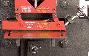
BAR/PLATE SHEARING
Your Ironworker machine will include a bar/plate shear as a standard feature. The bar/plate shear will provide a distortion and burr free shear cut to mild steel bar or plate stock as listed in the Ironworker Specifications section of this Manual as well as described on the capacity labels positioned at the Shearing Station. The Shearing Station on the Edwards Ironworker allows for straight or angled cutting applications. The material hold down adjusts with a simple hand crank to safely restrain the material being cut.
Setup
Standard bar/plate shears are factory tuned to proper clearances and are
ready to begin shearing operations. Shear blades are wearing parts and
will need to be maintained or replaced over time. When maintaining or
replacing your shear blades it is important to make sure the machine is
turned off. Failure to power down your machine could result in injury
to the operator performing the work. To setup bar/plate shear station
when maintaining or replacing blades, please refer to the following steps.
Remove
and replace stationary blade:
1. Remove the material hold-down assembly from the Ironworker frame by
removing the return spring and bolts that secure the assembly to the Ironworker
frame.
2. Remove blade bolts located under the feed table. Remove the stationary
blade.
3. With blade removed, clean blade pocket of any dirt or debris
4. Your shear blades have multiple cutting surfaces that can be flipped
and rotated prior to full replacement of the part. Rotate the stationary
blade to new cutting surface and reinstall in blade pocket.
5. Tighten the stationary blade back into the blade pocket.
Remove
and replace movable blade:
1. Remove the drop-off guard from the rear of the Ironworker frame.
2. Power on the machine and inch the moving center down to reveal bade
bolts for the moving blade.
3. With bolts exposed, turn machine off and disconnect from power source.
4. Remove blade bolts and remove blade from the blade pocket.
5. With blade removed, clean blade pocket of any dirt or debris.
6. Your shear blades have four cutting surfaces that can be used prior
to full replacement of the part. Rotate the movable blade to new cutting
surface and reinstall in blade pocket.
7. Tighten the movable blade back into the blade pocket.
8. Replace the drop-off guard to the rear of the frame.
9. Return the machine to power and turn on to automatically return the
moving center to its neutral position.
10. With a feeler gauge, check shear blade for correct operating clearance.
See the Care and Periodic Maintenance section of the Owners Manual for
tolerance adjustment instructions. Failure to maintain clearance will
damage shear blades and support brackets.
11. Replace and secure the material hold-down assembly and return spring
to the Ironworker frame.
Safe Operation
Please observe the following guidelines when operating the Bar/Plate Shear
Station
· Never exceed
the capacities of the machine or tooling as described in the Ironworker
specifications or listed at the tooling station.
· Check shear blade clearance at every tooling change or extended shear
operation. Maintain correct operating clearance at bar shear and angle
shear stations. See the Care and Periodic Maintenance section of your
Owners manual for tolerance adjustment instructions. Failure to maintain
clearance will damage shear blades and support brackets.
· Tighten the clamp handle to fully clamp the material hold-down on the
material being cut.
· Do not stack material to cut in the shear station.
· Perform complete shear operations only- partial shear cuts may jam the
drop off side of the frame and could result in breakage and operator injury.
· Use shearing aids when working with small items at the shear station.
Bar Shearing
Operation
When familiar with the setup and safe operation of the Shear Station,
clear the feed table of the shear station of any tools or debris prior
to powering the machine on. When clear, power the machine up and place
the material to be sheared on the feed table. Push the material under
the material hold-down and into the blade area. Position your material
to the desired cut and lower the material hold-down. Tighten the hand-wheel
to secure the material in the feed table. Clear your hands from the working
area and depress the foot pedal to activate the shear station. When the
cut is complete, release the foot pedal to return the shear blades to
their neutral position. Reverse the hand-wheel to raise the material hold-down
and remove your material.
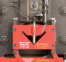
ANGLE
SHEARING
Your Ironworker may include an angle iron shear as a standard feature.
The angle shear will provide a distortion and burr free shear cut to mild
steel angle stock as listed in the Ironworker Specifications section of
this Manual as well as described on the capacity labels positioned at
the Angle Shearing Station. The Angle Shearing Station on the Edwards
Ironworker allows for straight cutting applications. An oversized material
hold down adjusts with a simple thumb crank to safely restrain the material
being cut.
Setup
Standard angle shears are factory tuned to proper clearances and are ready
to begin shearing operations. Shear blades are wearing parts and will
need to be maintained or replaced over time. When marinating or replacing
your shear blades it is important to make sure the machine is turned off.
Failure to power down your machine could result in injury to the operator
performing the work. When maintaining or replacing blades please refer
to the following.
Remove
and replace stationary blade:
1. Remove the material hold-down assembly from the Ironworker frame by
removing the bolts that secure the guard/hold-down assembly to the Ironworker
frame.
2. Remove blade bolts located behind the guard. Remove the stationary
blades.
3. With blades removed, clean blade pocket of any dirt or debris.
4. Your shear blades have multiple cutting surfaces that can be used prior
to full replacement of the part. Rotate the stationary blades to new cutting
surface and reinstall in blade pocket.
5. Tighten the stationary blades back into the blade pocket.
6. Replace and secure the material hold-down and guarding to the Ironworker
frame.
Remove
and replace movable blade:
1. Remove the angle shear drop-off guard from the rear of the Ironworker
frame.
2. Power on the machine and inch the moving center down to reveal blades
bolts for the moving blade.
3. With bolts exposed, turn machine off and disconnect from power source.
4. Remove blade bolts and remove blade from the blade pocket.
5. With blade removed, clean blade pocket of any dirt or debris.
6. Your shear blades have multiple cutting surfaces and tow radius options
that can be used prior to full replacement of the part. Rotate the movable
blade to the appropriate radius and new cutting surface and reinstall
in blade pocket. See fig. For correct radius designation.
7. Tighten the movable blade back into the blade pocket.
8. Replace the drop-off guard to the rear of the Ironworker frame.
9. Return the machine to power and turn on to automatically return the
moving center to its neutral position.
10. With a feeler-gauge, check shear blade for the correct operating clearance.
See the Care and Periodic Maintenance section in your Owners Manual for
tolerance adjustment instructions. Failure to maintain clearance will
damage shear blades and support brackets.
11. Replace and secure the material guard and hold-down assembly to the
Ironworker frame.
Safe Operation
Please observe the following guidelines when operating the Angle Shear
Station
· Never exceed
the capacities for the machine or tooling as described in the Ironworker
specifications or listed at the tooling station.
· Check shear blade clearance at every tooling change or extended shear
operation. Maintain proper operating clearance at bar shear and angle
shear stations. Failure to maintain clearance will damage shear blades
and support brackets.
· Fully engage the material hold-down with the material being cut.
· Do not stack material to cut in the shear station.
· Perform complete shear operations only- partial shear cuts may jam the
drop off side of the frame and could result in breakage and operator injury.
· Do not shear angle smaller than the hold-down will accommodate.
Angle
Shearing Operation
When familiar with the setup and safe operation of the Angle Shear Station,
clear station of any tools or debris prior to powering the machine on.
When clear, power the machine up and place the material to be sheared
into the material hold-down. Push the material through the angle hold-down
and into the blade area. Position your material to the desired cut and
lower the material hold-down. Tighten the thumb screw to secure the material
in the angle shear. Clear your hands from the working area and depress
the foot pedal to activate the shear station. When the cut is complete,
release the foot pedal to automatically return the shear blades to their
neutral position. Reverse the thumb screw to raise the material hold-down
and remove your material.
 Safety Guard pulled up for photo purposes
COPER-NOTCHER
TOOLING (IF STANDARD EQUIPMENT)
Notch tooling will provide a distortion and burr free, three sided shear
cut to mild steel bar, plate or angle stock as listed in the Ironworker
Accessories section of this Manual as well as described on the capacity
labels positioned at the Notching Station. The Notching Station on the
Edwards Ironworker allows for shaped, straight or angled notch cutting
applications.
Setup
When installing or adjusting notch tooling, always wear protective safety
glasses and make sure the machine is turned off. Failure to power down
your machine could result in injury to the operator performing the work.
Your Notching Station is equipped with one, three sided top notcher blade
and three, four sided bottom blades. The top blade is mounted to the moving
"center" of the Ironworker, while the bottom three blades are secured
into a base housing. If ordered as a factory installed option, your notcher
assembly is setup for immediate operation. To setup your Notching station
please observe the following steps.
1. Swing
the notcher guard assembly up and away from the notcher table.
2. Install the top notcher blade with the keyway up and the "foot" of
the blade facing the center of the machine. Secure the top blade using
the two ½" socket head cap screws. Tighten bolts.
3. Install the notcher table assembly to the base table. The notcher table
includes three blades secured within the table housing. Install with the
open "U" facing the center of the machine. The guide foot of the top blade
should be centered within the base table blades.
4. Loosely secure the table from the underside of the base with four ½"
bolts and washers (provided).
5. Check for top and bottom blade alignment by powering up the machine
and slowly inching down the top blade to meet the bottom blades within
the foot pedal. Power the machine off.
6. Using a feller gauge, adjust the clearance between the perimeter of
the top and bottom blades to allow for .010 clearance on all three sides.
7. In the event that the top and bottom blades are not aligned, simply
loosen the bolts under the table allowing the table to be moved to center
the top blade within the bottom blades. When aligned, tighten the table
bolts to secure the table.
8. Adjust the four set screws at the sides of the notcher table to engage
the base notcher table to the base table. Lock the four 3/8" nuts in place
to secure the set screws in place. These added fixtures are to provide
additional support to the base table during the notching operation.
9. Swing the notcher guard back in place.
Safe Operation
Please observe the following guidelines when operating the Notcher Station.
· Never exceed
the capacities of the machine or tooling as described in the Ironworker
specifications or listed at the tooling station.
· Check notcher blade clearance at every tooling change or extended notcher
operation. Maintain .010 clearance between top and bottom notcher blades
at all times. Failure to maintain clearance will damage blades and support
pockets.
· Cut with a minimum two of three sides of the blade surfaces engaging
the material being notched. Cutting on one blade surface may overload
the blades and result in tooling damage or injury to the Operator. See
figures A, B, and C.
· Do not stack material to cut in the notcher station.
· Perform complete notch operations only- partial notch cutes may jam
the drop off side of the tooling and could result in breakage and operator
injury.
· Use notching aids when working with small items at the notcher station.
Notching
Operation
When familiar with the setup and safe operation of the Notcher Station,
clear the feed table of the notcher station of any tools or debris prior
to powering the machine on. When clear, power the machine up and place
the material to be notched on the feed table. Push the material under
the tooling guard and into the blade area. Position your material to the
desired cut. Clear your hands from the working area and depress the foot
pedal to activate the notcher station. When the cut is complete, release
the foot pedal to automatically return the top notcher blade to the neutral
position.
COPER-NOTCHER
TOOLING (IF OPTIONAL)
Optional Notcher tooling will provide a distortion and burr free, three-sided
shear cut to mild steel bar, plate, or angle stock as listed in the Ironworker
Accessories section of this Manual as well as described on the capacity
labels positioned at the Notching Station. The Notching Station on the
Edwards Ironworker allows for shaped, straight or angled notch cutting
applications.
Setup
Optional tooling and accessories fit within the open station of the machine.
When changing any tooling, always wear protective safety glasses and make
sure the machine is turned off. Failure to power down your machine could
result in injury to the operator performing the work. Your Notching Station
is equipped with one, three sided top notcher blade and three, four-sided
bottom blades. The top blade is mounted to the moving "center" of the
Ironworker, while the bottom three blades are secured into a base housing.
If ordered as a factory installed option, your notcher assembly is setup
for immediate operation. If ordered as an option, the open cavity of the
machine must be cleared of any existing tooling, material or debris prior
to tooling installation. To setup your Notching Station, please observe
the following steps.
1. Swing
the notcher guard assembly up and away from the notcher table.
2. Install the top notcher blade with the keyway up and the "foot" of
the blade facing the center of the machine. Secure the top blade using
the two 3/8" socket head cap screws. Tighten bolts.
3. Install the notcher table assembly to the base table. The notcher table
includes three blades secured within the table housing. Install with the
open "U" facing the center of the machine. The guide foot of the top blade
should be centered within the base table blades.
4. Loosely secure the table from the underside of the base with four bolts
and washers (provided).
5. Check for top and bottom alignment by powering up the machine and slowing
inching down the top blade to meet the bottom blades with the foot pedal.
Power the machine off.
6. Using the feeler gauge, adjust the clearance between the perimeter
of the top and bottom blades to allow for .010 clearance on all three
sides.
7. In the event that the top and bottom blades are not aligned, simply
loosen the bolts under the table allowing the table to be moved to center
the top blade within the bottom blades. When aligned, tighten the table
bolts to secure the table.
8. Adjust the four set screws at the sides of the notcher table to engage
the base notcher table to the base table. Lock the four 3/8" nuts in place
to secure the set screws in place. These added fixtures are to provide
additional support to the base table during the notching operation.
9. Swing the notcher guard back in place.
Safe Notcher
operation
· Never exceed the capacities of the machine or tooling as described in
the Ironworker specifications or listed at the tooling station.
· Check notcher blade clearance at every tooling change or extended notcher
operation. Maintain .010 clearance between top and bottom notcher blades
at all times. Failure to maintain clearance will damage blades and support
pockets.
· Cut with a minimum two or three sides of the blade surfaces engaging
the material being notched. Cutting on one blade surface may overload
the blades and result in tooling damage or injury to the Operator. See
figures. (right)
· Do not stack material to cut in the notcher station.
· Perform complete notch operations only- partial notch cuts may jam the
drop off side of the tooling and could result in breakage and operator
injury.
· Use notching aids when working with small items at the notcher station.
Notching
Operation
When familiar with the setup and safe operation of the Notcher Station,
clear the feed table of the notcher station of any tools or debris prior
to powering the machine on. When clear power the machine up and place
the material to be notched on the feed table. Push the material under
the tooling guard and into the blade area. Position your material to the
desired cut. Clear your hands from the working area and depress the foot
pedal to activate the notcher station. When the cut is complete, release
the foot pedal to automatically return the top notcher blade to the neutral
position.
 Safety Guard pulled up for photo purposes
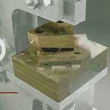
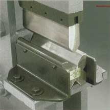
V-Notch
Tooling (OPTIONAL)
Optional V-Notch tooling will provide a distortion and burr free, two-side,
92 degree shear cut to mild steel bar, plate or angle stock. Common use
of this tooling is in the fabrication of angel iron frames. Please review
capacity labels positioned at the V-Notching Station.
Setup
Optional tooling and accessories fit within the open station of the machine.
When changing any tooling, always wear protective safety glasses and clothing
and make sure the machine is turned off. Failure to power down your machine
could result in injury to the operator performing the work. Your V-Notch
is equipped with one, two-sided top notcher blade and two, four-sided
bottom blades. The top blade is mounted to guide pins and return springs
of the tooling base. The moving "center" of the Ironworker, pushes on
the top V-Notch blade via the accessory push block. If ordered as a factory
installed option, your V-Notcher assembly is set up for immediate operation.
If ordered as an option, the open cavity of the machine must be cleared
of any existing tooling, material or debris prior to tooling installation.
To setup your V-Notching station please observe the following steps.
1. Remove
all tooling and guarding from the open station.
2. Install the push back supplied with the V-Notcher assembly. The V-shaped
end of the push block should be pointing away from the machine. Secure
the push block with bolts provided.
3. Place the V-Notcher assembly on the Ironworker support table with the
V pointing away from the machine.
4. Loosely secure the table from the underside base with four ½" bolts
and washers (provided).
5. Check for push block and top block and top blade alignment by powering
on the machine and slowly inching down the push block to meet the top
blade with the foot pedal. Power the machine off.
6. In the event that the push block ands top blade are not aligned, simply
loosen the bolts under the table allowing the table to be moved to center
the push block centerline to the top blade. When aligned, tighten the
table bolts to secure the table.
7. Install the V-Notcher guard with the bolts provided.
Safe Operation
Please observe the following guidelines when operating the V-Notcher Station.
· Never exceed
the capacities of the machine or tooling as described in the Ironworker
specifications or listed at the tooling station.
· Check V-Notcher blade clearance at every tooling change or extended
notcher operation. Maintain .010 clearance between top and bottom notcher
blades at all times. Failure to maintain clearance will damage blades
and support pockets.
· Cut with a minimum of two sides of the blade surfaces engaging the material
being notched. Cutting on one blade surface may overload the blades and
result in tooling damage or injury to the Operator.
· Do not stack material to cut in the V-Notcher station.
· Perform compete notch operations only- partial notch cuts many jam the
drop off side of the tooling and could result in breakage and operator
injury.
· Use notching aids when working with small items at the notching station.
V-Notching
Operation
When familiar with the setup and safe operation of the V-Notcher Station
clear the feed table of the notcher station of any tools or debris prior
to powering the machine on. When clear, power the machine up and place
the material being notched on the feed table. Push the material under
the tooling guard and into the blade area. Position your material to the
desired cut. Clear you hands from the working area and depress the foot
pedal to activate the notcher station. When the cut is complete, release
the foot pedal to automatically return the top notcher blade to the neutral
position.
 Safety Guard removed for photo purposes
OVER SIZE
PUNCH TOOLING (OPTIONAL)
Your Ironworker is capable of punching oversize holes in material listed
in the Ironworker Accessories section of this Manual. Standard and custom
tooling is available to allow for flange or leg down punching of angle
sections.
Setup
Optional tooling and accessories fit within the open or standard punch
station of the machine. When changing any tooling, always wear protective
safety glasses and make sure the machine is turned off. Failure to power
down your machine could result in injury to the operator performing the
work. To setup your Over Size Punch Tooling station please follow the
following steps.
1. Swing
the Punch Stripper assembly up from the standard punch by loosening the
stripper assembly bolts from the Ironworker frame.
2. Remove the standard punch holder from the operating center and the
standard die table from the support table base.
3. Secure the oversize punch holder to the operating center with the bolts
provided.
4. Place the oversize die tables on the support table base and loosely
install 4 bolts (provided) through the underside of the support table
into the oversize die tables.
5. Install new oversize die and tighten set screw. If loading a shaped
die, align the whistle spot with the set screw and tighten.
6. Install new oversize punch and tighten punch nut with wrench. If using
a shaped punch, align the locating keystock of the punch with the corresponding
slot within the punch stem assembly and tighten the punch nut with the
wrench.
7. Check for punch and die alignment by powering up the machine and slowing
inching the punch to meet the die with the foot pedal. Check to see that
the punch is centered in the die.
8. In the event that the punch and die are not aligned, simply loosen
the bolts under the table allowing the table to be moved to center to
the die. When aligned, tighten the table bolts to secure the table.
9. Swing the stripper bar back in place allowing for minimal clearance
between the top of the material and the bottom of the stripper and tighten
the stripper bolts.
Safe Operation
Please observe the following guidelines when operating the Oversize Punch
Station.
· Always
use safety glasses and factory supplied guards when operating your Ironworker.
· Read, understand and follow punching tolerances shown in the Punch section
of this manual.
· Never exceed the capacities of the machine or tooling as described in
the Ironworker specifications or listed at the tooling station.
· The thickness of the material you are punching should not exceed the
diameter of the punch being used.
· Follow manufacturers punch and die clearance recommendations as shown
in the Punching section of this manual.
· Check punch and die alignment after every tooling change or extended
punch operation.
· Adjust the punch stripper supplied with your Edwards Ironworker to allow
for material positioning and material stripping.
· Do not stack material to punch in the punching station.
· Use one or two drops of oil at the punch to aid the stripping material
from the punch as well as to extend the life of the punch tooling.
· Punch complete holes only- partial holes will side load the punch tooling
and could result in punch breakage and operator injury.
· Use punching aids when working with small items at the punch station.
Oversize
Punch Tooling Operation
When familiar with the setup and safe operation of the oversize punch
station, clear the punch station of any tools or debris prior to powering
the machine on. When clear, power the machine up and place the material
to be punched between the punch and die. Check to see that your material
is spanning the stripper plate and that adequate material is available
beyond the stripper area to safely position the material. Clear your hands
from the working area and depress the foot pedal to move the punch the
material and into the die. When the punch is complete, release the foot
pedal to automatically strip the material from the punch and return the
punch to its neutral position.
 Safety Guard removed for photo purposes
241 &
28XX EXTRA LARGE PUNCH TOOLING (OPTIONAL)
Your Ironworker is capable of punching materials as listed in the Ironworker
Specifications section of this Manual as well as described on the capacity
labels positioned at the Punch Station. The punch station on the Edwards
Ironworkers allows for a wide variety of punching and stamping applications.
Standard and custom tooling is available to allow for flange or leg down
punching of standard angle sections. Refer to the accessory pages of your
manual for further information.
Setup
Optional tooling and accessories fit within the open or standard punch
station of the machine. When changing any tooling, always wear protective
safety glasses and make sure the machine is turned off. Failure to power
down your machine could result in injury to the operator performing the
work. To setup your 241 Punch Tooling please observe the following steps.
1. Remove
the standard punch stripper from the ironworker frame, punch holder from
the operating center and the standard die table from the support table
base.
2. Secure the 241 punch holder to the operating center by first removing
the stud from the holder. Place the holder to the operating center with
the tapped hole positioned to the outside of the center. Install holder
with two ½" SHCS bolts and tighten. Install stud to holder with four 3/8"
SHCS bolts and tighten.
3. Place the 241 die table and slug chute on the support table base and
loosely install four ½" bolts (provided) through the underside of the
support table into the 241 die table.
4. Install new oversize die and tighten set screw. If loading a shaped
die, align the whistle spot with the set screw and tighten.
5. Install new 241 punch and tighten with spanner wrench. If using a shaped
punch, align the locating keystock (not provided) of the punch with the
corresponding slot within the punch stem assembly and tighten the punch
nut with the wrench.
6. Check for punch and die alignment by powering up the machine and slowly
inching down the punch to meet the die with the foot pedal. Check to see
that the punch is centered in the die.
7. In the event that the punch and die are not aligned, simply loosen
the bolts under the table allowing the table to be moved to center the
die. When aligned, tighten the table bolts to secure the table.
8. Install and secure the 241 stripper bar to the ironworker frame allowing
for minimal clearance between the top of the material to be punched and
the bottom of the stripper.
Safe Operation
Please observe the following guidelines when operating the 241 Punch Station.
· Always
use safety glasses and factory supplied guards when operating your Ironworker.
· Read, understand and follow the punch size tolerances shown in Fig,
1 (page 7).
· Never exceed the capacities of the machine or tooling as described in
the Ironworker specifications or listed at the tooling station.
· The thickness of the material you are punching should not exceed the
diameter of the punch being used.
· Follow manufacturer's punch and die operating clearance recommendations
as shown on page 7.
· Check punch and die alignment after every tooling change or extended
punch operation.
· Adjust the punch stripper supplied with your Edwards Ironworker to allow
for material positioning and material stripping.
· Do not stack material to punch in the punching station.
· Use one or two drops of oil at the punch to aid in stripping material
from the punch as well as to extend the life of the punch tooling.
· Punch complete holes only- partial holes will side load the punch tooling
and could result in punch breakage and operator injury.
· Use punching aids when working with small items at the punch station.
241 Punch
Tooling Operation
When familiar with the setup and safe operation of the oversize punch
station, clear the punch station of any tools or debris prior to powering
the machine on. When clear, power the machine up and place the material
to be punched between the punch and die. Check to see that your material
is spanning the stripper plate and that adequate material is available
beyond the stripper area to safely position the material. Clear your hands
from the working area and depress the foot pedal to move the punch through
the material and into the die. When the punch is complete, release the
foot pedal to automatically strip the material from the punch and return
the punch to its neutral position.
 Safety Guard removed for photo purposes
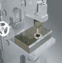
PEDESTAL
DIE TOOLING (STANDARD)
Your Ironworker will punch materials listed in the Ironworker Specifications
section of this Manual as well as described on the capacity labels positioned
at the Punch Station. Pedestal Die tooling is available in standard and
oversize configurations to allow for 2"x2"x1/4" max. angle to be punched
leg down at the punch station. Standard 2"x1/4"max. channel sections may
be web punched and special offset dies are available for punching close
to web/flange unions. Refer to the accessory pages of your Manual for
further information.
Setup
Optional tooling and accessories fit within the open or standard punch
station of the machine. When changing any tooling, always wear protective
safety glasses and make sure the machine is turned off. Failure to power
down your machine could result in injury to the operator performing the
work. To setup your Pedestal Die Tooling station please observe the following
steps.
1. Swing
the Punch Stripper up from the punch by loosening the stripper assembly
bolts.
2. Remove die by loosening the set screw at the front of the punch table
and then lifting die from the die holder. If the die resists removal gently
tap the die from the underside of the punch table to loosen the die for
removal.
3. Remove standard die table from the fixed table base by removing the
four bolts.
4. Install new Pedestal Die Table to fixed table base with the two ½"
bolts provided. Loosely secure bolts with the supplied washers and nuts
from the underside of the table.
5. Install die and tighten set screw. If loading a shaped die, align the
whistle spot with the set screw and tighten.
6. Install punch and tighten punch nut with wrench. If using a shaped
punch, align the locating keystock of the punch with the corresponding
slot within the punch stem assembly and tighten the punch nut with the
wrench.
7. Check for punch and die alignment by powering up the machine and inching
down the punch to meet the die with the foot pedal. Check to see that
the punch is centered in the die.
8. In the event that the punch and die are not aligned, simply loosen
the bolts under the table allowing the table to be moved to center the
die. When aligned, tighten the Pedestal Die Table bolts to secure the
table.
9. Swing the stripper bar back in place allowing for minimal clearance
between the top of the material and the bottom of the stripper and tighten
the stripper bolts.
Safe Operation
Please observe the following guidelines when operating the Punch Station
· Read, understand
and follow the punch size tolerances shown in Fig.1 (page 7).
· Never exceed the capacities of the machine or tooling as described in
the Ironworker specifications or listed at the tooling station.
· The thickness of the material you are punching should not exceed the
diameter of the punch being used.
· Follow manufacturer's punch and die operating clearance recommendations
as shown on page 7.
· Check punch and die alignment after every tooling change or extended
punch operation.
· Adjust the punch stripper supplied with your Edwards Ironworker to allow
for material positioning and material stripping.
· Do not stack material to punch in the punching station.
· Use one or two drops of oil at the punch to aid in stripping material
from the punch as well as to extend the life of the punch tooling.
· Punch complete holes only- partial holes will side load the punch tooling
and could result in punch breakage and operator injury.
· Use punching aids when working with small items at the punch station.
Pedestal
Die Operation
When familiar with the setup and safe operation of the Pedestal Die Tooling
installed in the punch station, clear the punch station of any tools or
debris prior to powering the machine on. When clear, power the machine
up and place the material to be punched between the punch and die. Check
to see that your material is spanning the stripper plate and that adequate
material is available beyond the stripper area to safely position the
material. Clear your hands from the working area and depress the foot
pedal to move the punch through the material and into the die. When the
punch is complete, release the foot pedal to automatically strip the material
from the punch and return the punch to its neutral position.
 Safety Guard pulled up for photo purposes
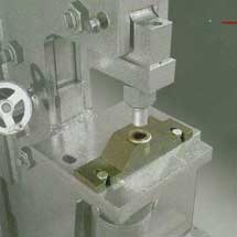
PIPE-
NOTCH TOOLING (OPTIONAL)
Optional Pipe-Notch tooling will provide a distortion and burr free notch
cut to mild steel pipe stock as listed in the Ironworker Accessories section
of this Manual as well as described on the capacity labels positioned
at the Pipe-Notching Station.
Setup
Optional tooling and accessories fit within the open station of the machine.
When changing any tooling, always wear protective safety glasses and make
sure the machine is turned off. Failure to power down your machine could
result in injury to the operator performing the work. Your Pipe-Notch
Station is equipped with one, top notcher die and one, bottom notcher
die. The top die is mounted within a spring loaded guide housing mounted
to the tooling base. The bottom die attaches to the face of the guide
housing and is machined with a saddle to aid in centering and guiding
pipe sections into the die housing. The moving "center" of the Ironworker,
pushes on the top Pipe-Notch blade via the accessory push block. If ordered
as a factory installed option, your Pipe Notcher assembly is setup for
immediate operation. If ordered as an option, the open cavity of the machine
must be cleared of any existing tooling, material or debris prior to tooling
installation. To setup your Pipe-Notching station please observe the following
steps.
1. Remove
all tooling and guarding from the open station.
2. Install the push block supplied with the Pipe-Notcher assembly. Secure
the push block with bolts provided.
3. Place the Pipe-Notcher assembly on the Ironworker support table with
the bottom die pointing away from the machine.
4. Loosely secure the table from the underside of the base with four ½"
bolts and washers (provided).
5. Check for push block and top die alignment by powering on the machine
and slowly inching down the push block to meet the top die with the foot
pedal. Power the machine off.
6. In the event that the push block and top die are not aligned, simply
loosen the bolts under the table allowing the table to be moved to center
the push block centerline to the top blade. When aligned, tighten the
table bolts to secure the table.
7. Power the machine on and jog the center down. The pipe dies will close
or bypass each other. The push block should not come in contact with the
die housing.
Safe Operation
Please observe the following guidelines when operating the Pipe Notcher
Station.
· Never exceed
the capacities of the machine or tooling as described in the Ironworker
specifications or listed at the tooling station.
· Keep the Pipe Notch tooling clean. When dirt or metal chips accumulate,
remove 5/16-18 x 1/2" limit screw located in the center at the rear of
punch. Lift out punch holder and two springs. Clean holder with solvent
or kerosene.
· Check Pipe Notcher blade clearance and alignment at every tooling change,
maintenance cycle or extended notcher operation. Maintain .010 clearance
between notcher blades at all times. Failure to maintain clearance will
damage blades and support pockets.
· Do not stack material to cut in the Pipe Notcher station.
· Perform complete notch operations only- partial notch cuts may jam the
drop off side of the tooling and could result in breakage and operator
injury.
· Use notching aids when working with small items at the notcher station.
Pipe-Notching
Operation
When familiar with the setup and safe operation of the Pipe Notcher Station
clear the feed table of the notcher station of any tools or debris prior
to powering the machine on. When clear, power the machine up and place
the material to be notcher on the feed table. Push the material under
the tooling guard and into the blade area. Position your material for
the desired cut. Clear your hands from the working area and depress the
foot pedal to activate the notcher station. When the cut is complete,
release the foot pedal to automatically return the top notcher blade to
the neutral position.
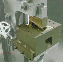
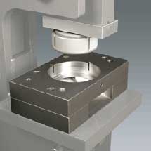
PRESS
BRAKE TOOLING (OPTIONAL)
Optional Beak tooling is available in 7", 8", 10" and 12" assemblies for
your Edwards Ironworker. Brake tooling will allow for the graduated bending
of 1/6", 3/16", 1/8", and ¼" flat, bar or angle stock up to 90 degrees.
This tooling is most effective when ordered with the factory installed
Electric Stroke Control feature.
Setup
Brake tooling can be accommodated in either the open or punch station
of the machine. When changing any tooling, always wear protective safety
glasses and make sure the machine is turned off. Failure to power down
your machine could result in injury to the operator performing the work.
Your Brake tooling is equipped with one mounting bracket to secure the
"punch" to the center of the machine, one "punch", one "4-way die", and
two bottom brackets that secure the "die" to the base table. The moving
"center" of the Ironworker, pushed the top punch into the shaped die to
bend the specified material. If ordered as a factory installed option,
your Brake assembly is setup for immediate operation. If ordered as an
option, the open or punch station must be cleared of any existing tooling,
material or debris prior to tooling installation. To setup your Brake,
please observe the following steps.
1. Remove
all tooling and guarding from the open or punch station.
2. Secure the Brake mounting bracket to the "center" with bolts provided.
The ½" tapped hole is positioned to the outside of the machine.
3. Position punch in the bracket so that the milled relief in the keyway
slips over the bracket bolt. Tighten set screws in the bracket to secure
the punch.
4. Place the die assembly on the Ironworker support table.
5. Loosely secure the two support brackets to the support table from the
underside of the base with four ½" bolts, nuts and washers (provided).
6. Check for punch and die alignment by powering on the machine and slowly
inching down the punch to meet the bottom die with the foot pedal. Power
the machine off.
7. In the event that the punch and die are not aligned, simply loosen
the bolts under the table allowing the die block to be moved to center
the punch. When aligned, tighten the table bolts to secure the table.
8. Select 1/16", 3/16", 1/8", or ¼" test material for bending. Rotate
your four-way die to your selected material thickness. Power the machine
on and jog the center down until the punch pushes the sample material
into the die. If the punch stops before the material has been formed to
a 90 degree angle, a small steel shim must be placed between the bottom
die and support table.
9. Re-install all guarding to the machine prior to machine use.
Safe Operation
Please observe the following guidelines when operating the Press Brake
Station.
· Never exceed
the capacities of the machine or tooling as described in the Ironworker
specifications or listed at the tooling station.
· Keep the brake tooling clean.
· Check Brake clearance and alignment at every tooling change, maintenance
cycle or extended Brake operation. Failure to maintain proper clearance
may damage punch, die and support brackets or adjacent tooling.
· Brake material towards the center of the brake length.
· Do not stack material in the Brake station.
· Use Brake aids when working with small items at the Brake station.
· When not in use, remove the Brake die from the holder.
Press
Brake Operation
When familiar with the setup and safe operation of the Brake, clear the
station of any tools or debris prior to powering the machine on. When
clear, power the machine up and place the material to be "broken" on top
of the bottom die. Bending material to the front or back of the brake
die may damage your Ironworker. Position your material for the desired
bend in the middle. Clear your hands from the working area and depress
the foot pedal to lower the punch the desired amount. You can hold a protractor
in front to see what angle you are bending to. If your Ironworker machine
has electronic stroke control like an Edwards, you can adjust it to stop
the punch at the exact depth you want to repeat the same bend angle, again
and again. When the brake operation is complete, release the foot pedal
to return the punch to the neutral position.
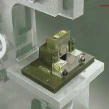
ROD SHEAR/MULTI-SHEAR
TOOLING (OPTIONAL)
Optional "bump-die" shear tooling is available for your Edwards Ironworker.
Rod Shear or Multi Shear Tooling will provide distortion and burr free
cuts to mild steel rod, square, bar and small angle stock as listed in
the Ironworker Accessories section of this Manual.
Setup
Optional "bump-die" tooling and accessories fit within the open or punch
stations of the machine. Verify recommended location per Ironworker model
below. When changing any tooling, always wear protective safety glasses
and make sure the machine is turned off. Failure to power down your machine
could result in injury to the operator performing the work. Edwards "bump-die"
tooling consists of a housing which holds a stationary blade, a moving
blade, return springs and a push block. The moving "center" of the Ironworker,
pushes on the top moving blade via the push block to shear the material.
If ordered as a factory installed option, your "bump-die" assembly is
setup for immediate operation. If ordered as an option, the open or punch
cavity of the machine must be cleared of any existing tooling, material
or debris prior to tooling installation. To setup your Rod Shear or Multi
Shear tooling installation please observe the following steps.
1. If your
machine is an Edwards, use the following locations:
25 Ton: open station on right side
50 Ton Pro: punch station
55 Ton: open station on right side or punch station
65 Ton: punch station or open cavity in upper middle
75 Ton: punch station
100 Ton: Deluxe: punch station
120 Ton: open cavity
2. Remove
all tooling and guarding from the appropriate open, punch or open cavity
station.
3. Place the "bump-die" assembly on the Ironworker support table with
the push block in line with the moving center.
4. Loosely secure the table from the underside of the base with four 1/2"
blots and washers (provided).
5. Check for push block and moving center alignment by powering on the
machine and slowly inching down the center to meet the push block with
the foot pedal. Power the machine off.
6. In the event that the push block and top die are no aligned, simply
loosen the bolts under the table allowing the bump-die to be moved to
center the push block with the moving center. When aligned, tighten the
table bolts to secure the table.
7. Power the machine on and jog the center down. The moving blade will
close or bypass the fixed blade. The push block should not come in contact
with the die housing.
Safe Operation
Please observe the following guidelines when operating any Rod Shear or
Multi-Shear bump-die tooling.
· Never exceed
the capacities of the machine or tooling as described in the Ironworker
specifications or listed at the tooling station.
· Keep the tooling clean.
· Check blade clearance and alignment at every tooling change, maintenance
cycle or extended tooling operation. Maintain .010 clearance between blades
at all times. Failure to maintain clearance will damage blades and support
pockets.
· Do not stack cut material.
· Perform complete shearing operation only- partial cuts may jam the tooling
and could result in breakage and operator injury.
· Use shearing aids when working with small items at the Rod Shear or
multi Shear Tooling station.
Rod Shear/Multi-Shear
Operation
When familiar with the setup and safe operation of the Rod Shear or Multi-Shear
Tooling, clear the work area of any tools or debris prior to powering
the machine on. When clear, power the machine up and insert material through
the tooling guard and into the blade area. Position your material for
the desired cut. Clear your hands from the working area and depress the
foot pedal to activate the tooling station. When the cut is complete,
release the foot pedal to automatically return the tooling to the neutral
position.
ELECTRIC
STROKE CONTROL (STANDARD)
Electric stroke control is standard on most Ironworker machines including
all but the Edwards 25 ton. Stroke control enables the Ironworker operator
to shorten up and down stroke with minor adjustment of two hand screws.
Utilize stroke control to control precision bending with your brake tooling,
control stroke when using embossing or bump dies or simply increase production
from your punch, notch or shear stations.
Setup
Stroke control is currently offered only as a factory installed option
and arrives fully setup for immediate use. Always wear protective safety
glasses and make sure the machine is turned off when adjusting the electric
stroke control option. Failure to power down machine could result in injury
to the operator performing the work.
Safe Operation
Please observe the following guidelines when adjusting the electric stroke
control function.
· Always
use safety glasses and factory supplied guards when operating your Ironworker.
· Read, understand and follow punching, notching and shearing tolerances
as described in related chapters of this manual.
· Never exceed the capacities of the machine or tooling as described in
the Ironworker specifications or listed at the tooling station.
· Keep limit switches free of dirt and grime.
· Never remove stroke retention nuts from factory setting.
· Never reverse stroke limit switches.
Electric
Stroke Control Operation
Set upstroke for rapid cycling of your punching, shear and notching stations.
· Power machine
on and use the jog function of your electric foot pedal to bring tooling
down to rest just above the material being worked.
· Turn machine off.
· Adjust upper handle with tapered collar to engage limit switch.
· Power machine on. Tooling will stay in set position.
· Remove material from tooling station and cycle machine. Tooling should
return to pre-set position.
· Place material in tooling station and cycle machine.
To Set
Upstroke for faster cycle time for punching operation
· Power machine on and use the jog function of your electric foot pedal
to bring ram down to engage tooling. Jog ram to push bump die tooling
to the specified depth.
· Turn machine off.
· Adjust lower handle with tapered collar to engage limit switch.
· Power machine on. Ram will return to top of stroke.
· Cycle machine to insure proper stroke depth.
· Place material in tooling station and cycle machine.
To Set
Downstroke for press brake operation
· Power machine on and use the jog function of your electric foot pedal
to bring ram down to engage tooling with material.
· Jog ram to push brake die tooling to the specified depth/ brake angle.
· Turn machine off.
· Adjust lower handle with tapered collar to engage limit switch.
· Power machine on. Ram will return to top of stroke.
· Place test material in tooling station and cycle machine to insure proper
stroke depth and material brake.
NOTE: For using other optional equipment such as the various Back Gauges, Angle Gauge, Gaging Tables, Stripper Reducer, Urethane Stripper, Rotating Turret, please see their individual instructions.
IMPORTANT
MAINTANENCE FOR YOUR HYDRAULIC IRONWORKER MACHINE
1. Grease your machine minimum of once for every 8 hours of use. This
is the most important thing you can do to make your machine last a long
time.
2. Change your hydraulic oil a few months after you get your machine to
get the break-in oil out of the machine. If you cant change the oil regularly,
please change it at least once. It will make a big difference. Heavily
used machines should have their oil changed at least once per year. Your
hydraulic cylinder, hydraulic pump and hydraulic valve will appreciate
it. Edwards recommends using viscosity 46 hydraulic oil.
3. Change your punches and blades when they get dull to prevent from overloading
the machine.
4. Make sure you are using your machine on level ground to prevent overloading
one side.
TROUBLESHOOTING
YOUR HYDRAULIC IRONWORKER MACHINE
Your Edwards Ironworker is designed for years of trouble-free use. In
the event of operational problems please refer to the following troubleshooting
strategies prior to contacting your Edwards Dealer. All remedial actions
are to be performed with the Ironworker powered off and power to the hydraulic
supply turned off.
| Problem | Solution |
| Machine runs but will not cycle | Check rotation of motor Check correct amp/voltage to machine Check drive key is in place Check foot pedal cable obstruction |
| Machine cycles down but will not return to neutral position | Check rotation of motor Check return spring at valve Check foot pedal linkage |
| Machine turns off after short time in use | Check correct amp/voltage to machine |
| Electric stoke operator malfunction | Check correct amp/voltage to machine Check fuse at starter box Check fuse at transformer box Check for loose microswitch connections Check for damaged microswitch |
| Brass shavings below gib-pins and slides | Brass shavings are common and expected during the break-in period and after blade maintenance |
ELECTRICAL HOOKUP
Confirm the electrical supply coming to the terminal location that will power your Ironworker with a certified electrician prior to hooking up your machine. Confirm your electrical supply with the electrical specifications of the machine listed in your Operator Manual and located on the Ironworker starter box. It is critical that a qualified electrician install your machine as your Warranty protection does not cover mis-wiring of electrical components at your site.
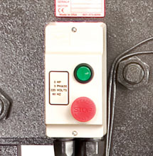
ELECTRICAL STARTER BOX
Have your electrician confirm the power supply coming into your facility and to the electrical terminal location. Provide the wiring diagrams to the electrician prior to initiating the electrical hookup of the machine.
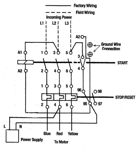
Typical 220 volts 1 phase Electrical Diagram shown below
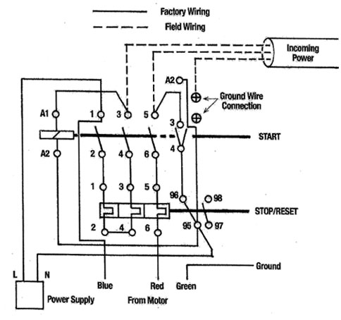
Power wiring
of Overload Relay for single phase motors shown above.
The overload relay is designed to speed tripping in case of uneven loading
or loss of one phase, therefore all 3 overload heaters must be used on
1 phase.
Incoming power hooks in on top of starter to #3 and #5. It does not matter
which lead goes to #3 or 5. But the ground wire does matter. The motor
should already be wired for correct rotation at the factory.
Typical 220/380/415/440/480 volts 3 phase Electrical Diagram shown below
For Manual
Control with Buttons in Cover.
Incoming power hooks in on top of #1, 3, 5. Motor rotation is clockwise
looking at the fan end of the motor. If rotation is wrong, switch line
2 and line 3 around.
Click
for Edwards Ironworker Machines
Click for How to use a Lathe Machine
Click for How to use a Milling Machine
Click for How to use a Band Saw Machine
Click for How to use a Surface Grinder Machine
Click for How to use a Drill Press Machine
Click for How to use a Sheet Metal Brake Machine
Click for the American Machine Tool Homepage
5862 Northwest Hwy
Chicago IL 60631 USA
Phone: 773-334-5000
Fax: 773-442-0314
Click to email us
American Machine Tools Corp.
All rights reserved
Offers from American Machine Tools Corporation include include Terms and Conditions shown on our website.
Liability is strictly limited to those warranties of fitness for purpose and safety as provided by the manufacturer.
Products and Logos in this website are trademarks or registered trademarks of their respective companies or mark holders.